Partial discharge (PD) testing is a cornerstone of high-voltage insulation diagnostics. For reliable measurements, selecting the right configuration for your test circuit is critical. This article explores the key setups and components used in PD measurements — with a focus on measuring impedance (ZmZ_m), high-frequency current transformers (HFCT), and signal handling techniques.
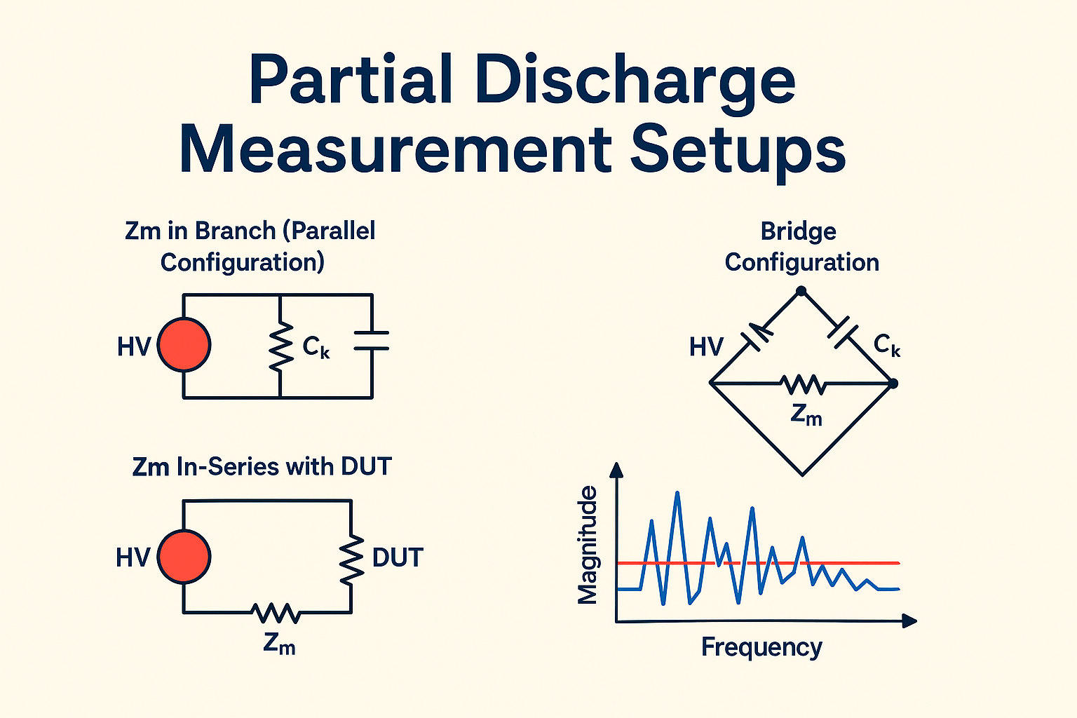
There are three main ways to integrate the measuring impedance Zm into a PD test circuit:
In this setup, Zm is placed parallel to the test object.
Safer for the impedance circuit in case of breakdown
Lower measurement sensitivity
Here, Zm is placed in series with the device under test (DUT).
High sensitivity
Exposes Zm to direct high-voltage events
A balanced bridge layout uses multiple Zm elements to reject common-mode noise.
Excellent for lab-grade sensitivity
Requires precise balance and matching components
The measuring impedance Zm converts high-frequency current pulses generated by PD events into voltage signals — which are easier to digitize and process.
Easier to amplify
Lower noise susceptibility
Most acquisition systems are voltage-based
Digital Signal Processing (DSP) works better in the voltage domain
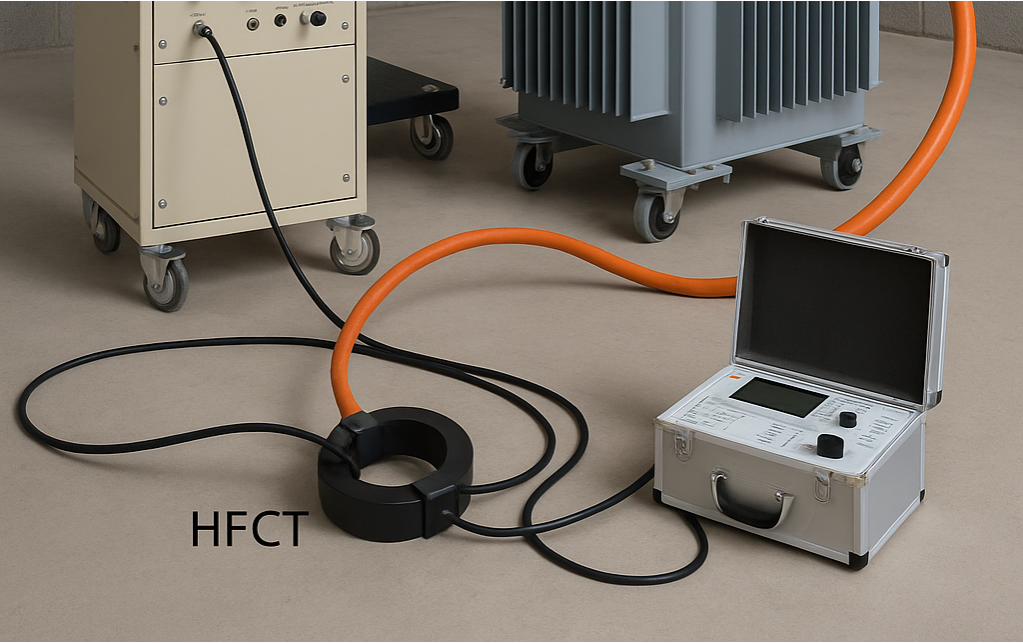
High-Frequency Current Transformers (HFCTs) detect PD pulses inductively — without direct electrical contact.
Non-invasive
High isolation
Broad frequency response (100 kHz – 100 MHz)
Can saturate under 50/60 Hz load
Requires integration and careful calibration
A typical Zm behaves like a high-pass filter:
Zm = R + jωL
High Zm : Greater sensitivity, but may saturate
Low Zm : Lower sensitivity but better performance under high current
Selecting the right Zm depends on your test object's expected discharge strength and background noise.
The coupling capacitor ( Ck ) provides a parallel path for high-frequency PD signals to reach the sensor.
Higher Ck improves signal-to-noise ratio (SNR)
Larger Ck also demands more supply current
It directly affects pulse width: τ = RC
Controlling noise is critical in PD measurements. Common types include:
White Noise: Appears as a flat FFT spectrum
Switching Noise: Comes from inverters or power supplies
Sinusoidal Interference: From AM/FM signals or power-line carriers
Tip: Always perform a noise spectrum analysis (FFT) before beginning PD tests. A clean background is essential for accurate detection.
Accurate partial discharge testing relies on more than just instruments — it requires a thoughtful setup. Whether you choose a simple parallel Zm , a sensitive in-series configuration, or a lab-grade bridge network, each method has its pros and cons.
HFCTs offer non-intrusive sensing for environments where safety and isolation are key, while Zm based setups provide more direct voltage analysis.
None
روشهای نوین در پایش تخلیه جزئی: تلفیق تحلیل زمانی-فرکانسی و الگوریتمهای آماری مطالعه حاضر چهارچوبی برای ادغام تکنیکهای کلاسیک (نمودارهای فاز-بار) با روشهای مدرن (پردازش سیگنال غیرخطی و یادگیری ماشین) را با تمرکز بر کالیبراسیون سیستمهای اندازهگیری PD کاهش نویز با فیلترهای تطبیقی طبقهبندی خودکار نقصها ارائه میدهد.
ادامه مطلبPartial Discharge, PD Measurement, q(u) plot, q(t) plot, HFCT, Oscilloscope, Statistical Fingerprint, 3CFRD are all caught up in this article as a starter package.
ادامه مطلب